

Building a network
VLANs
Split the ports of a switch into networks that do not see each other, carry several of them on one cable, and route from one to another.
A VLAN (virtual LAN) splits the ports of a switch into separate networks. Two devices on ports of different VLANs do not reach each other, even on the same switch, until a router joins the two networks. In PixelCake a VLAN is a number from 1 to 4094, set port by port on the switches, and the engine applies it to every packet it follows.
Access and trunk ports
Each port of a switch works in one of two ways:
- An access port is in one VLAN. It is where an end device is connected: a PC, a printer, an access point. What leaves an access port carries no tag.
- A trunk port carries several VLANs on one cable, each frame with the tag of its VLAN. It joins two switches, or a switch and a device that expects tags. A trunk lists the VLANs it carries; a trunk with an empty list carries them all.
To set a port, open the window of the switch with a double click, go to the “Ports” tab and choose the port. Under “Port mode” choose “Access (end device)” and type the number in “VLAN (single)”, or choose “Trunk (between switches)” and type the list in “VLANs (comma-separated)”, for example 10, 20. Nothing changes until you press “Save”.
VLAN 1 and the ports you did not touch
A switch with no VLAN on any of its ports forwards everything as it comes: all its ports are one network. As soon as one port has a VLAN, the switch applies VLANs port by port, as real hardware does, and every port nobody set is an access port in VLAN 1.
This is the most common surprise. On the sample network “Office: two networks and a router”, put the two PCs in VLAN 10, one port at a time:
pixelcake> interface 1 access 10 on SW-Office
port 1 on SW-Office is now an access port in VLAN 10
  SW-Office now applies VLANs port by port: the ports you did not set are in VLAN 1
pixelcake> ping PC-2 from PC-1
Pinging PC-2 (192.168.10.12) from PC-1...
Ping failed (blocked): request: VLAN 10 does not leave through port 2 on SW-Office: it is in the default VLAN 1
  dropped at: SW-Office
pixelcake> interface 2 access 10 on SW-Office
port 2 on SW-Office is now an access port in VLAN 10
pixelcake> ping PC-2 from PC-1
Pinging PC-2 (192.168.10.12) from PC-1...
Reply from 192.168.10.12: hops=3 time=3ms
pixelcake> ping Web-01 from PC-1
Pinging Web-01 (192.168.20.10) from PC-1...
Ping failed (blocked): request: VLAN 10 does not leave through port 8 on SW-Office: it is in the default VLAN 1
  dropped at: SW-Office
The two PCs reach each other again, but not the servers: port 8, the cable to Router-1, was left in VLAN 1, and the gateway of the PCs is on the other side of it. Put it in VLAN 10 too:
pixelcake> interface 8 access 10 on SW-Office
port 8 on SW-Office is now an access port in VLAN 10
pixelcake> ping Web-01 from PC-1
Pinging Web-01 (192.168.20.10) from PC-1...
Reply from 192.168.20.10: hops=5 time=7ms
A switch also answers on its own address in VLAN 1 only: a switch whose ports are all in other VLANs is managed from a network of its own, as SW-Core and SW-Offices are in the company sample.
One trunk, several VLANs
In the sample network “Company: offices, Wi-Fi, servers and DMZ” the desks of the offices are in VLAN 10 and the access point of the Wi-Fi in VLAN 20, on the same switch, SW-Offices. One cable takes both VLANs to SW-Core: port 8 of SW-Offices is a trunk for VLANs 10 and 20. SW-Core takes the trunk on its port 1 and gives each VLAN an access port towards Router-Core.
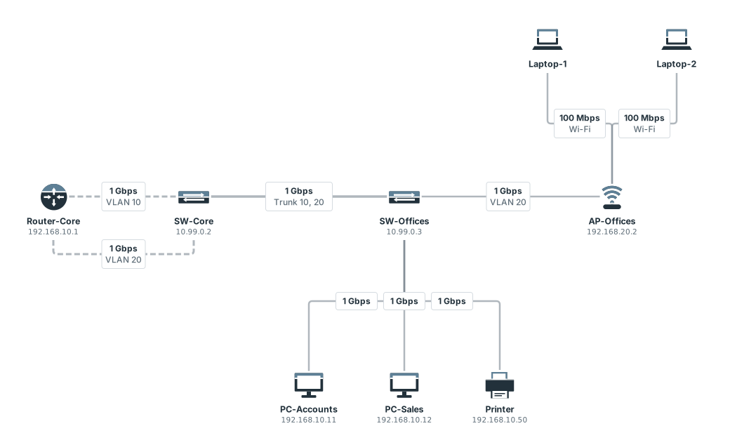
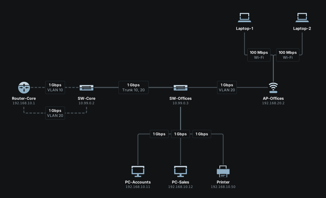
show vlans lists every VLAN with the ports it is on, and the trunks that carry it:
pixelcake> show vlans
VLAN   MEMBERS
1      SW-Offices (ports 5,6,7), SW-Core (ports 2,3,4,5,6), SW-Servers (ports 6,7)
10     SW-Offices (ports 1,2,3; trunk 8), SW-Core (port 7; trunk 1)
20     SW-Offices (port 4; trunk 8), SW-Core (port 8; trunk 1)
30     SW-Servers (ports 1,2,3,4,5,8)
Take VLAN 20 off the trunk and the Wi-Fi is cut off from the rest of the network. The reason names the port; the laptops lose their address as well, because their requests for one travel in VLAN 20 to the DHCP server on Router-Core:
pixelcake> interface 8 trunk 10 on SW-Offices
port 8 on SW-Offices is now a trunk carrying VLANs [10]
pixelcake> ping Web-ERP from AP-Offices
Pinging Web-ERP (192.168.30.30) from AP-Offices...
Ping failed (blocked): request: VLAN 20 does not leave through port 8 on SW-Offices: it is a trunk carrying VLANs [10]
  dropped at: SW-Offices
pixelcake> ping Web-ERP from Laptop-1
Pinging Web-ERP (192.168.30.30) from Laptop-1...
Ping failed (error): request: Laptop-1 has no address: no DHCP server answers on its network
pixelcake> interface 8 trunk 10,20 on SW-Offices
port 8 on SW-Offices is now a trunk carrying VLANs [10,20]
pixelcake> ping Web-ERP from Laptop-1
Pinging Web-ERP (192.168.30.30) from Laptop-1...
Reply from 192.168.30.30: hops=7 time=11ms
From one VLAN to another
Two VLANs are two networks: a packet goes from one to the other only through a router, or a firewall, with a port in each. Each of those ports has an address of its network, and that address is the gateway of the devices of the VLAN. In the company sample Router-Core has port 1 on VLAN 10 (192.168.10.1), port 2 on VLAN 20 (192.168.20.1) and port 3 on VLAN 30, the servers (192.168.30.1).
A trace shows both: the VLAN the packet is in at each switch, and the route the router takes.
pixelcake> trace Web-ERP from PC-Sales
Tracing route to Web-ERP (192.168.30.30) from PC-Sales:
  1  ○ PC-Sales (PC)
  2  ○ SW-Offices (Switch)  — VLAN 10
  3  ○ SW-Core (Switch)  — VLAN 10
  4  ○ Router-Core (Router)  — routed: 192.168.30.0/24 is on port 3
  5  ○ SW-Servers (Switch)  — VLAN 30
  6  ● Web-ERP (Server)
Trace complete: destination reached.
The addresses of the ports of a router are explained in Addresses and gateways.
The VLANs a device knows
Besides the VLAN of each port, a device has a list of VLANs of its own, in the VLAN group of the “General” tab of its window:
- on a switch, it is the VLANs the switch knows: frames of any other VLAN are dropped. An empty list means all of them;
- on any other device, it is the VLANs its interface accepts tagged, on a trunk port. An empty list means untagged traffic only. A device that declares VLANs must be connected to a port of one of them.
Most drawings never need it: the VLAN of the ports is enough. In the terminal the list is changed with add vlan and remove vlan (reference).
Names for VLANs
A VLAN can be given a name, once for the whole project. In Settings → Network, under “Project VLANs”, the table lists the VLANs the board uses: type a name next to each, or add another with “Add VLAN”, then save. The name then appears next to the number wherever the window of a switch or of a port shows it, as VLAN 10 “Offices”. The terminal and the reasons of the engine keep the numbers.
The sample networks bring the names of their VLANs with them.
In the terminal
| To | Type |
|---|---|
| see every VLAN and where it is | show vlans |
| see the ports of a switch, with the VLAN of each | show interfaces SW-Offices |
| put a port in a VLAN | interface 3 access 10 on SW-Offices |
| make a port a trunk | interface 8 trunk 10,20 on SW-Offices |
| give a port back its default | interface 3 default on SW-Offices |
Every command, with its options and more examples, is in Interfaces and VLANs.
Limits
Limits
- Routing between VLANs needs a port of a router, or of a firewall, in each VLAN. Sub-interfaces on one port (a "router on a stick") are not modelled.
- The untagged traffic of a trunk is always VLAN 1: there is no native VLAN to choose.
- Spanning tree is not simulated: a drawing with redundant cables between switches is walked without loops, but no port is blocked.
- There is no MAC learning, no VTP or GVRP, no voice VLAN, no private VLAN and no double tagging.